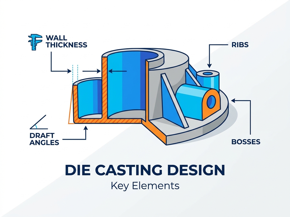
Poor part design wrecks manufacturing operations. It forces extensive tooling modifications, drives up scrap rates, and delays time-to-market. Engineers and procurement teams often fight to balance complex structural requirements with the physical limits of the die casting process. When component geometry fights fluid dynamics and thermal cooling principles, you get a cascade of defects. Internal porosity, localized shrinkage, and premature tool wear become daily headaches on the shop floor. Adhering to strict Design for Manufacturability (DFM) principles is the only reliable way to guarantee predictable production and high-yield output. Optimizing critical features like wall thickness, draft angles, ribs, and bosses stops structural failure before it starts. It ensures molten metal flows uniformly throughout the cavity. Implementing these design guidelines early in the engineering phase kills unnecessary secondary operations, slashes cycle times, and gives you a clear framework for picking a highly capable manufacturing partner.
Uniformity is Critical: Maintaining consistent wall thickness is the primary defense against uneven cooling, shrinkage, and internal porosity in the die casting process.
Draft Dictates Tool Life: Properly calculated draft angles prevent galling, ensure clean part ejection, and significantly extend the lifespan of the steel die.
Strategic Reinforcement: Utilizing ribs and fillets increases structural stiffness and improves material flow without the penalties of added mass or thick cross-sections.
NADCA Guidelines as a Benchmark: Utilizing standardized North American Die Casting Association (NADCA) tolerances ensures repeatable quality and lowers tooling development costs.
DFM as a Selection Criteria: A manufacturer’s ability to provide rigorous, upfront DFM feedback is a primary indicator of their capability to handle complex die casting projects successfully.
The Role of Design in the Die Casting Process
A successful component design facilitates minimized cycle times, zero-defect production runs, and maximized tool longevity. Engineers must eliminate unnecessary secondary machining by designing parts that cast to net shape or near-net shape. The core objective aligns the geometric features of the part with the thermodynamic realities of liquid metal injection. You cannot force metal to do what physics forbids.
Physics of Liquid Metal Injection
Understanding how liquid metal behaves under extreme pressure and velocity inside the die cavity dictates proper component design. Molten alloy shoots into the steel die at high speeds, often exceeding 40 meters per second at the gate. The material navigates complex geometries before it begins to solidify. Thermal balance and controlled solidification determine the structural integrity of the final part. If the metal cools too rapidly in thin sections, it restricts flow to thicker areas, causing incomplete fills. Areas with excessive mass retain heat longer, leading to uneven cooling rates that destroy mechanical properties.
Common Design-Induced Defects
Ignoring established design rules creates a direct path to specific manufacturing defects. Recognizing these failure modes allows engineers to adjust geometry before cutting expensive tool steel.
Cold shuts and misruns happen when molten metal solidifies before completely filling the cavity. This typically stems from walls that are too thin or flow paths that stretch too far from the gate.
Sink marks and localized shrinkage porosity develop in overly thick bosses and heavy sections. The interior metal cools and contracts slower than the exterior skin, pulling material away from the center and leaving voids.
Warping and dimensional instability result from uneven thermal cooling across parts with drastically varying cross-sectional mass. The part twists as it cools on the shop floor.
Galling and drag marks appear on vertical surfaces lacking sufficient taper. This damages both the component finish and the die steel during ejection, leading to costly polishing and downtime.
Evaluating design choices requires balancing upfront tooling complexity against long-term production efficiency. Intricate sliding cores or secondary machining operations might solve a geometric challenge on paper. However, optimizing the base design for straight-pull ejection yields superior long-term reliability and lower scrap rates in actual production.
Wall Thickness: Balancing Strength and Material Flow
Wall thickness acts as the most critical variable in any die casting project. It dictates material flow, cooling time, and the ultimate structural soundness of the component. Designing walls that are too thin restricts metal flow, while walls that are too thick invite internal voids and extend cycle times.
Optimal Ranges by Alloy
Different alloys possess unique fluidity and thermal characteristics. You must apply specific baseline wall thickness parameters to achieve optimal results.
Alloy Type
Common Grades
Optimal Wall Thickness
Characteristics & Application Notes
Aluminum
A380, ADC12, A360
1.5mm - 3.0mm
Provides an optimal weight-to-strength ratio. Maintains sufficient velocity to fill the cavity without premature freezing.
Zinc
Zamak 3, Zamak 5
1.0mm - 2.5mm
Exceptionally high fluidity. Capable of ultra-thin walls down to 0.75mm in highly controlled environments.
Components rarely feature a single, uniform wall thickness throughout their entire geometry. When varying wall thicknesses are necessary, engineers must design gradual transitions. A strict engineering requirement is the use of a 3:1 transition ratio to maintain uniform cooling rates. Abrupt changes in cross-sectional mass cause turbulent metal flow and create stress concentrations. Gradual tapers ensure the material solidifies evenly and prevent the formation of internal hot tears.
Volumetric Shrinkage and Thermal Contraction
As molten metal transitions to a solid state, it undergoes volumetric shrinkage. Aluminum typically shrinks by approximately 0.6%, while zinc shrinks by roughly 0.7%. Improper wall design exacerbates this natural contraction. When a heavy section sits isolated by thinner surrounding walls, the thin walls freeze first. This cuts off the flow of additional molten metal required to feed the shrinking heavy section. This isolation inevitably leads to internal voids and shrinkage porosity.
Implementation Risks and Trade-offs
Designers must weigh the consequences of their dimensional choices. Overly thick walls increase cycle times due to longer required cooling periods and drastically raise the probability of internal porosity. Overly thin walls risk misruns, incomplete cavity filling, and require excessively high ejection forces that warp the part. Thinner walls reduce material usage and part weight, but they demand higher injection pressures, specialized gating systems, and robust tooling to withstand the increased mechanical stress.
Draft Angles: Ensuring Clean Ejection and Tool Longevity
Draft angles are slight tapers applied to vertical surfaces of a component, parallel to the direction of die opening. They serve as a fundamental requirement to release the part from the steel mold without causing mechanical damage to the tool or the casting.
Calculating Minimum Draft Requirements
Draft requirements follow a formulaic approach based on wall depth, alloy type, and the specific location of the feature relative to the tooling.
Inside Walls (Cores): As molten metal cools, it naturally shrinks away from the outer cavity and constricts tightly onto internal steel cores. This thermal shrinkage requires greater draft on inside walls to break the friction during ejection. A minimum of 1.5° to 2.0° is typically required for internal features.
Outside Walls (Cavity): Because the material shrinks away from the external die steel, outside walls face less resistance during ejection. These surfaces generally require less draft, typically ranging from 0.5° to 1.0° minimum.
Standard vs. Precision Tolerances
Designing for standard draft based on NADCA Commercial Standards ensures reliable production and standard tooling maintenance cycles. Specifying precision draft demands tighter tapers, rigorous process control, specialized friction-reducing die coatings, and significantly more frequent tool maintenance. Precision draft increases the risk of galling and necessitates slower ejection speeds, which impacts overall production efficiency and drives up unit costs.
Impact of Surface Finish
Final surface finish requirements heavily influence draft calculations. Textured, polished, or painted surfaces require increased draft angles to prevent dragging, scuffing, or marring during ejection. A standard engineering rule adds 1° of draft for every 0.02mm of texture depth. Failure to accommodate texture depth with adequate draft results in the part shearing the texture off the die wall. This ruins both the component finish and the tooling.
Risk Mitigation for Zero-Draft Features
When functional requirements demand zero-draft surfaces, engineers must utilize moving slide cores or plan for secondary machining. Slide cores pull away from the part before the main die opens, allowing for zero-draft side actions. This adds significant complexity to the mold base, increases maintenance requirements, and introduces flash lines where the slide meets the main cavity. Secondary CNC machining provides perfectly cylindrical, zero-draft holes but introduces additional handling and cycle time. Treat these options as secondary solutions when standard draft cannot apply.
Ribs and Fillets: Enhancing Stiffness Without Adding Mass
Instead of increasing overall wall thickness to achieve structural integrity, engineers should utilize ribs and fillets. This approach increases stiffness and improves material flow without the severe penalties of added mass, extended cooling times, and shrinkage porosity.
Designing Ribs for Optimal Flow
Ribs must be proportioned correctly relative to the walls they support to prevent cosmetic and structural defects.
Rib Feature
Design Guideline
Manufacturing Impact
Rib Thickness
50% to 70% of adjoining wall thickness
Prevents localized mass concentration and sink marks on the opposite cosmetic surface.
Rib Height
Maximum 3x to 4x the adjoining wall thickness
Prevents filling issues and rapid thermal fatigue at the deep root of the die cavity.
Rib Draft
Minimum 1.5° per side
Ensures clean release from deep, narrow channels in the die steel without snapping.
The Critical Role of Fillets and Radii
Sharp internal corners act as the leading cause of structural failure, stress concentrations, and turbulent material flow. Molten metal does not navigate sharp 90-degree turns efficiently. It requires smooth transitions to maintain velocity and prevent air entrapment. Internal radii should be at least 1x the wall thickness, while external radii should measure at least 1.5x to 2x the wall thickness. Generous fillets distribute mechanical stress across a wider area, preventing premature cracking under load.
The "Inscribed Circle" Method
Evaluating joint intersections where ribs meet walls is critical to preventing localized mass accumulation. Engineers use the inscribed circle method to analyze these junctions. By drawing the largest possible circle within the cross-section of the intersection, you can visualize the thermal mass. If the inscribed circle at the joint is significantly larger than the inscribed circle of the standard wall, it represents a hot spot prone to shrinkage porosity. Adjusting rib thickness and fillet radii reduces this mass concentration.
Evaluation Dimensions: Weight vs. Complexity
Utilizing ribs effectively reduces overall part weight and material consumption. You must balance this against tooling complexity. Complex rib networks require extensive EDM (Electrical Discharge Machining) milling to burn the deep, narrow channels into the die steel. Engineers must optimize rib placement to provide maximum structural benefit with the simplest possible tooling geometry.
Bosses and Holes: Fastening and Assembly Considerations
Bosses serve as mounting points and standoffs for assembly. Because they inherently require localized increases in material thickness, they are highly susceptible to shrinkage and porosity if not designed according to strict DFM rules.
Boss Design Rules
Proper boss design integrates structural support while minimizing thermal mass.
Wall Thickness of Boss: Limit the wall thickness of the boss itself to 1x to 1.2x the thickness of the adjoining main wall. Overly thick boss walls guarantee internal voids that expose themselves during subsequent tapping operations.
Draft Requirements: Internal draft for cored holes within bosses is critical. Depending on the depth of the hole, internal draft typically ranges from 1.0° to 3.0° to allow the core pin to extract without bending or galling.
Structural Support: Freestanding bosses lack mechanical stability and disrupt metal flow. Tie bosses to adjacent side walls using connecting ribs, gussets, or brackets. This provides structural rigidity and creates runner paths that help feed molten metal into the boss during injection.
Cored Holes vs. Secondary Machining
Engineers must decide whether to cast holes directly into the part using core pins or to drill and tap them post-cast.
Casting holes directly reduces cycle time, eliminates secondary operations, and minimizes material usage. Core pins are subject to immense thermal shock and mechanical wear, requiring frequent replacement. Casting very small holes under 3mm for aluminum is generally avoided as thin core pins easily warp or snap under injection pressure.
Drilling holes after casting increases cycle times and requires additional fixtures. It provides tight tolerances, perfectly cylindrical zero-draft surfaces, and eliminates the risk of core pin breakage during the casting cycle.
Mitigating Shrinkage Around Heavy Sections
When large bosses are unavoidable, engineers must utilize core-outs beneath or around the heavy section. By removing non-functional material from the center or base of a large boss, the design maintains a uniform wall thickness throughout the feature. This eliminates localized hot spots, prevents sink marks on adjacent surfaces, and ensures a dense, porosity-free structure suitable for load-bearing threads.
The Tooling Interface: Designing for Parting Lines, Gates, and Ejector Pins
A part cannot exist in isolation from the tool that manufactures it. Understanding how the component interfaces with the die halves, gating system, and ejection mechanism is vital for achieving cosmetic and functional requirements.
Parting Line Selection
The parting line is the precise perimeter where the two halves of the die meet. Its location dictates draft orientation, flash formation, and the cosmetic appearance of the final component. Engineers must place the parting line on the largest cross-sectional area of the part to allow for straightforward ejection. Placing the parting line along a sharp edge rather than a flat surface makes it easier to trim flash cleanly without marring cosmetic faces.
Gating and Overflow Systems
The gating system acts as the pathway through which molten metal enters the cavity. Overflows are external pockets designed to catch trapped air and the first front of cold metal. The designer must accommodate these features by providing accessible areas along the part perimeter where gates and overflows can attach and subsequently trim. Design concessions, such as adding flat tabs or extending non-cosmetic edges, facilitate clean gate removal via trim dies without damaging the functional geometry of the part.
Ejector Pin Placement and Witness Marks
Ejector pins are steel rods that push the solidified part off the die core. These pins leave unavoidable round indentations known as witness marks on the part surface. Engineers must design flat landing areas on non-cosmetic, internal surfaces to accommodate these pins. Placing ejector pins on angled surfaces causes the pins to slip or bend. Placing them on thin walls risks punching through the material. Proper placement ensures mechanical force distributes evenly during ejection without compromising part function or external aesthetics.
Evaluating Die Casting Partners for DFM Expertise
The success of a complex manufacturing project relies heavily on the technical capability of the chosen foundry. Selecting a partner based solely on initial quotes often leads to unresolved design flaws and high production scrap rates.
Solution Categories
The industry divides between transactional foundries and consultative manufacturing partners. Transactional foundries cut steel and cast parts exactly as drawn, regardless of inherent design flaws. This inevitably results in high reject rates and repeated tool modifications. Consultative partners conduct deep DFM analysis upfront. They challenge the design and propose geometric optimizations to ensure manufacturability before any steel is cut.
Technical Validation Tools
A qualified partner utilizes advanced engineering software to validate the design.
Mold Flow Simulation: Tools like MAGMAsoft or ProCAST simulate the injection of molten metal, identifying air entrapment, cold welds, and shrinkage zones. This allows engineers to adjust gating and wall thickness virtually.
Thermal Analysis: Simulating the die cooling cycles helps optimize the placement of internal water lines. This ensures uniform cooling, prevents hot spots, and minimizes overall cycle times.
Transparent DFM Reporting: Capable partners provide clear, detailed 3D markup reports that highlight problematic areas and suggest specific wall, draft, and radius optimizations.
Tooling Guarantees and Quality Assurance
A partner's confidence in the finalized, optimized design translates directly into tooling lifetime guarantees. Foundries that enforce rigorous DFM are typically willing to guarantee H13 tool steel dies for 100,000 shots or more. They validate the initial production run through stringent First Article Inspection (FAI), utilizing coordinate measuring machines (CMM) for dimensional accuracy and X-ray testing to verify the absence of internal porosity.
Conclusion
Effective die casting design begins by aligning part geometry with metal flow, solidification, tooling, and ejection requirements. Uniform wall thickness helps reduce porosity and distortion, while gradual transitions prevent localized thermal stress. Adequate draft angles support clean ejection and longer die life, and properly proportioned ribs, fillets, and bosses improve stiffness without creating excessive material buildup.
Parting lines, gates, overflows, ejector pins, and cored holes should also be considered during the initial CAD stage rather than after tooling begins. Early DFM review, supported by mold-flow and thermal simulation, can identify filling problems, hot spots, and unnecessary secondary operations before steel is cut.
The most manufacturable design is not simply the lightest or most complex geometry. It is a balanced component that meets functional requirements while supporting stable production, consistent quality, shorter cycle times, and controlled tooling costs.
FAQ
Q: What is the minimum wall thickness for aluminum die casting?
A: The standard minimum wall thickness for aluminum is typically 1.5mm. Specialized high-pressure processes and vacuum assistance can achieve thinner walls down to 1.0mm. Doing so requires exceptional process control, increases the risk of cold shuts, and accelerates thermal fatigue and wear on the die steel.
Q: Why are draft angles necessary in the die casting process?
A: Draft angles are necessary because molten metal undergoes thermal shrinkage as it solidifies, constricting tightly around internal die cores. Draft provides a slight taper that breaks the mechanical friction between the part and the tool, allowing for clean ejection without galling, dragging, or distorting the component.
Q: How do you prevent porosity in die cast parts?
A: Porosity is prevented by maintaining uniform wall thickness to ensure even cooling. Engineers utilize core-outs beneath heavy bosses to eliminate localized thermal mass. Proper venting, optimized overflow design, and vacuum-assisted casting systems help evacuate trapped air from the cavity before the metal freezes.
Q: Can you die cast undercuts without secondary operations?
A: Yes, undercuts can be cast using moving slide cores and mechanical side-actions integrated into the tooling. These mechanisms significantly increase the complexity and upfront cost of the mold, require more frequent maintenance, and often extend the overall cycle time of the casting process.
Q: What is the standard tolerance for die cast components?
A: Baseline NADCA standard tolerances for linear dimensions typically start at ±0.25mm for the first 25mm, with an additional ±0.025mm for each subsequent 25mm. Flatness and concentricity tolerances depend heavily on part geometry, wall uniformity, and the specific alloy's shrinkage characteristics during cooling.
With so many years' hard work and development, Ningbo Joyo Metal has built a competitive supply chain in the market to serve the distinguished customers all over the world.
About Us
Your partner for customized metal components/parts manufacturing

 English
 العربية
 Français
 Русский
 Español
 Português
 Deutsch
 italiano
 日本語
日本語 한국어
한국어 Nederlands
 Tiếng Việt
 ไทย
ไทย Polski
 Türkçe
 አማርኛ
አማርኛ ພາສາລາວ
 ភាសាខ្មែរ
 Bahasa Melayu
 ဗမာစာ
ဗမာစာ தமிழ்
தமிழ் Filipino
 Bahasa Indonesia
 magyar
 Română
 Čeština
 Монгол
 қазақ
қазақ Српски
 हिन्दी
 فارسی
فارسی Kiswahili
 Slovenčina
 Slovenščina
 Norsk
Norsk Svenska
 українська
 Ελληνικά
 Suomi
Suomi עברית
עברית Dansk
Dansk Afrikaans
 Gaeilge
 Eesti keel
 latviešu
 Беларуская мова
 Български
 Català
 Lietuvių
 Lëtzebuergesch
 Македонски