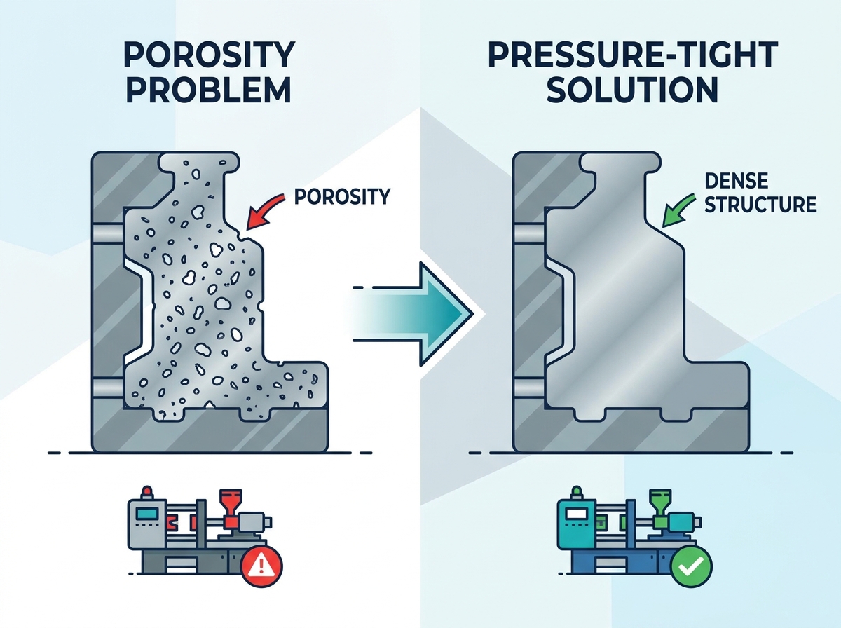
Component failure in fluid-handling, pneumatic, and hydraulic applications carries immense operational risks. Microscopic leak paths trigger catastrophic system failures, product recalls, and unacceptable scrap rates. The core problem lies in the inherent nature of high-pressure manufacturing: porosity. Both gas and shrinkage porosity directly compromise structural integrity and hermetic sealing, turning otherwise functional parts into liabilities.
Achieving pressure-tight standards requires a holistic engineering approach. You cannot rely on basic defect sorting at the end of the production line. Manufacturers must implement proactive Design for Manufacturability (DFM), advanced process controls, and strategic post-processing techniques. By understanding the root causes of voids and applying targeted interventions, engineers produce components that consistently meet stringent pressure requirements.
Root Cause Identification is Critical: Differentiating between gas porosity (trapped air) and shrinkage porosity (thermal contraction) dictates the required engineering intervention.
Design Dictates Yield: Uniform wall thickness, optimized gating, and strategic overflow placement are foundational; process tweaks cannot out-perform poor part design.
Advanced Technologies Mitigate Risk: Vacuum-assisted casting and squeeze casting significantly reduce gas entrapment and improve material density for critical applications.
Post-Casting Interventions are Valid but Costly: Vacuum impregnation effectively seals micro-porosity, but should be treated as a secondary safeguard rather than a substitute for process control.
Where Defects Originate: The Die Casting Process Explained for Pressure-Tight Parts
The Mechanics of Porosity Formation
During the injection phase, molten metal enters the die cavity at extreme velocities, often exceeding 100 feet per second. This violent filling creates severe turbulence, causing ambient air and vaporized die lubricants to become trapped within the solidifying metal. We identify this as gas porosity, which presents as smooth, spherical voids under X-ray inspection. The machine applies massive intensification pressure at the end of the stroke to compress these gases, but the bubbles remain trapped within the aluminum matrix.
The solidification phase introduces a completely different mechanical failure mode. As molten aluminum cools from 1200°F down to room temperature, it undergoes volumetric contraction. If the cooling rate is uneven across the component geometry, or if isolated heavy sections cool slower than surrounding thin walls, the material literally tears itself apart internally as it shrinks. This creates shrinkage porosity, appearing as jagged, interconnected voids. These internal cavities destroy structural integrity and create direct channels for fluid to escape.
Why Pressure-Tight Applications Fail
Interconnected subsurface porosity creates active leak paths. A raw cast part might look perfectly solid on the surface because the rapid cooling against the H13 tool steel creates a dense outer skin. However, secondary CNC machining operations strip away this protective layer, exposing the internal voids. When these exposed pores connect across a pressure boundary, hydraulic fluid or compressed air escapes, completely compromising the seal.
Establishing clear success criteria on the shop floor is mandatory. You must define acceptable porosity limits based on size, distribution, and specific location. A 0.5mm isolated pore might be perfectly acceptable in a non-structural mounting flange. However, that exact same pore located in an O-ring groove or a high-pressure mating surface will cause an immediate field failure. Critical zones require near-zero defect tolerances.
Melt Quality and Hydrogen Control
Dissolved hydrogen gas in the molten aluminum acts as a massive multiplier for gas porosity. Hydrogen is highly soluble in liquid aluminum but has almost zero solubility in the solid state. As the metal cools and freezes in the die, the hydrogen is violently forced out of solution, forming microscopic gas bubbles that become permanently trapped in the casting structure.
Effective melt preparation stops this at the source. Foundry operators use rotary degassing equipment to inject an inert gas, typically argon or nitrogen, deep into the holding furnace to purge dissolved hydrogen. We follow this with aggressive fluxing to remove suspended oxides and non-metallic inclusions. Operators must perform real-time density index testing on the shop floor to verify melt cleanliness before a single shot is fired, ensuring hydrogen levels remain strictly within acceptable limits.
Design and Engineering Controls for Defect Reduction
Metallurgical Alloy Selection for Pressure Tightness
Alloy composition dictates fluidity and the specific solidification shrinkage range. Alloys with a narrow freezing range exhibit superior feeding characteristics, drastically reducing the likelihood of shrinkage porosity. Silicon content acts as the primary driver for improving fluidity and minimizing hot tearing during the rapid freezing cycle.
Alloy Grade
Silicon Content
Castability
Pressure Tightness Rating
Primary Application
A380
7.5% - 9.5%
Excellent
Moderate
General purpose housings, brackets
A360
9.0% - 10.0%
Good
Excellent
Hydraulic manifolds, fluid pumps
A356
6.5% - 7.5%
Excellent
High (Heat Treatable)
Structural aerospace, pressure vessels
When engineering leak-tight components, A360 or high-silicon alloys consistently outperform standard A380. A360 offers lower shrinkage characteristics, making it significantly easier to achieve a dense, pressure-tight internal structure. A356 remains the go-to choice for high-integrity applications requiring subsequent T6 heat treatment for maximum mechanical yield strength.
Predictive Engineering: Mold Flow and Thermal Simulation
Running advanced simulation software like MAGMASOFT or Flow-3D is a hard requirement during the DFM phase. These computational fluid dynamics tools allow tooling engineers to visualize the exact filling patterns and thermal gradients before cutting a single block of expensive tool steel. You identify the failure points in the virtual environment, not on the production floor.
Simulation accurately predicts air entrapment zones, cold shuts, and isolated hot spots. Engineers adjust gating designs, modify cooling line placements, and alter part geometry based on the software output. This predictive capability eliminates the old "pour and pray" mentality, reducing tooling development time and preventing catastrophic design failures.
Optimizing Wall Thickness and Transitions
Uniform wall thickness drives directional solidification. When walls maintain a consistent thickness, the molten metal cools evenly, allowing the machine's intensification pressure to effectively feed shrinkage voids as the material contracts. You must design gradual transitions between different cross-sections to prevent severe stress concentrations and erratic cooling rates.
Isolated heavy sections act as thermal hot spots, remaining liquid long after the surrounding thinner walls have frozen solid. These areas are guaranteed to develop shrinkage porosity because the feeding path is physically cut off by the frozen thin sections. You mitigate these hot spots by coring out thick areas, adding metal savers to the CAD model, or utilizing localized high-pressure heat sinks directly in the die steel.
Gating and Runner System Design
The runner system dictates metal velocity and controls turbulence during the critical filling phase. A properly engineered runner ensures a smooth, continuous flow of molten aluminum into the cavity, keeping the metal front intact and reducing air entrapment. Tooling engineers calculate the exact cross-sectional area of the runner to maintain the required flow rate without causing premature freezing.
Evaluating gate size and location requires balancing fill time against the risk of atomizing the molten metal. A gate that is too small forces the metal through at excessive velocities, causing atomization and severe gas porosity. A gate that is too large results in slow fill times and premature freezing, preventing the intensification pressure from feeding the casting during solidification.
Overflow and Venting Strategies
Strategic overflow placement captures the first, coldest, and most oxide-rich metal entering the cavity. By directing this degraded metal out of the main cavity and into external overflows, you pull porosity and inclusions completely out of the functional part geometry. Overflows also act as localized heat sources, maintaining die temperature in hard-to-fill areas.
Massive venting is required to evacuate ambient die cavity air before the metal freezes. Toolmakers utilize chill blocks, washburn vents, and deep venting channels to provide unrestricted pathways for air and vaporized lubricants to escape. If the trapped air cannot exit the cavity faster than the molten metal enters, it compresses and forms permanent gas porosity.
Advanced Die Casting Process Parameters and Technologies
Real-Time Shot Profile Control
Having the die casting process explained through injection phase control reveals the absolute necessity of precise parameter management. The first-phase speed utilizes a slow, controlled shot to advance the molten metal past the pour hole without creating a wave that folds over and traps air. The machine then triggers the second-phase speed, transitioning to a high-velocity fast shot for rapid cavity filling before the metal loses temperature.
The third phase, intensification pressure, makes or breaks pressure-tight components. The machine applies massive hydraulic pressure—often exceeding 10,000 PSI—during the final milliseconds of solidification. This forces additional liquid metal into the cavity to feed shrinkage voids and compresses any remaining trapped gases, ensuring a dense, sound structure.
Vacuum Assist Die Casting (VADC)
VADC utilizes industrial vacuum pumps to pull a high vacuum on the die cavity milliseconds before the shot sleeve advances. This mechanical system physically evacuates the ambient air and vaporized gases from the mold, drastically reducing the volume of gas available to be trapped. A specialized vacuum valve closes precisely as the molten metal reaches it, sealing the system and preventing aluminum from entering the vacuum lines.
VADC drastically reduces gas porosity, allowing for higher material density and the production of structural, heat-treatable components. However, you must account for the implementation realities. VADC requires significantly higher tooling costs, specialized vacuum blocks, rigorous daily maintenance, and it often extends the overall cycle time.
Squeeze Casting and Semi-Solid Metal Casting
Squeeze casting abandons the high-velocity approach of traditional methods, utilizing a much slower gate velocity combined with extreme, sustained pressure during the entire solidification phase. This laminar flow minimizes turbulence and maximizes feeding, virtually eliminating shrinkage porosity. The resulting components exhibit exceptional mechanical properties and guaranteed pressure tightness.
Semi-solid metal casting injects aluminum in a partially solid, partially liquid state—often resembling the consistency of toothpaste. This high-viscosity flow completely eliminates turbulence and air entrapment. Both squeeze casting and semi-solid methods serve as the standard for manufacturing highly critical components like hydraulic manifolds, brake calipers, and high-pressure vessels.
Thermal Management: Cooling Lines and Die Temperatures
Die temperature regulation controls the exact solidification rate of the casting. Tooling engineers design complex networks of water, oil lines, or conformal cooling channels to manage the thermal gradients within the H13 die blocks. Consistent die temperatures ensure repeatable part quality, prevent soldering, and minimize thermal fatigue cracking on the tool steel.
Localized cooling prevents hot spots in critical sealing areas. By directing high-pressure coolant through bubblers or jet cooling pins directly into thick sections or core pins, you accelerate the cooling rate in targeted zones. This forces the metal to freeze quickly, preventing shrinkage voids from forming in locations where pressure tightness is mandatory.
Post-Casting Solutions and Trade-Offs
Managing Machining Allowances and Tool Wear
Cast parts naturally develop a dense outer skin. The outer 0.015" to 0.020" of the casting cools rapidly against the chilled die steel, creating a fine-grained, highly dense layer. This skin resists leakage and provides excellent structural integrity.
To maintain pressure tightness, you must minimize the machining depth on all sealing surfaces. Removing too much material cuts right through the dense skin and exposes the porous internal structure, creating immediate leak paths. Furthermore, dull CNC tooling tears the aluminum surface rather than cutting it cleanly, which smears the metal and opens up closed subsurface pores. Machinists must maintain sharp cutting tools and optimized feed rates to preserve surface integrity.
Vacuum Impregnation: When to Use It
Vacuum impregnation uses anaerobic resins to seal micro-porosity after the part is cast and machined. Operators place the components in a vacuum chamber, evacuate the air from the internal pores, and introduce a specialized liquid resin. They then apply positive pressure to force the resin deep into the micro-voids. The parts are washed, and the resin cures into a permanent, hard plastic seal.
You must perform a strict cost-benefit analysis before relying on impregnation. While it effectively seals micro-porosity and saves scrap parts, it adds significant cost, logistics, and cycle time to the manufacturing process. Impregnation fixes micro-porosity and seals leak paths, but it does absolutely nothing to restore the structural strength lost to large macro-porosity voids.
Evaluating a Manufacturing Partner for High-Pressure Applications
Quality Standards and Acceptance Criteria
Manufacturing partners must operate under recognized standards for pressure-tight applications, such as those established by ASTM and NADCA. These standards define the exact testing methodologies, equipment calibration requirements, and acceptance criteria for various classes of structural castings.
You must establish clear Quality Assurance agreements (AQL) regarding permissible pore sizes in critical zones before issuing a purchase order. The agreement must explicitly define the inspection methods, acceptable defect sizes in millimeters, and the specific geometric locations where zero porosity is required to ensure reliable field performance.
Non-Destructive Testing (NDT) Capabilities
In-house X-ray and CT scanning capabilities are non-negotiable for porosity detection and volume analysis. These NDT methods allow quality engineers to inspect the internal structure of the casting without destroying the part. This verifies that the manufacturing process is consistently producing dense components and allows for rapid troubleshooting if defects appear.
Leak testing methodologies validate the final pressure tightness. Hydrostatic testing, pressure decay testing, and helium leak detection offer varying levels of sensitivity. The appropriate method depends entirely on the specific application requirements, the operating pressure of the fluid, and the allowable leak rate defined by the engineering drawing.
Process Capability (Cpk) and Traceability
A reliable foundry partner must demonstrate high process capability (Cpk > 1.33) for all critical parameters, including shot speed, intensification pressure, and die temperature. High Cpk values prove that the foundry runs a stable, predictable process that consistently produces parts within specification, rather than relying on end-of-line sorting to catch bad parts.
Shot monitoring systems and real-time process adjustments maintain this control. Modern die casting machines track the injection parameters for every single cycle, providing full traceability. If a shot deviates from the established limits, the system automatically segregates the suspect part, allowing for immediate corrective action by the process engineer.
Conclusion
Achieving pressure-tight components in die casting requires a comprehensive, heavily engineered strategy. Layering Design for Manufacturability, rigorous process control, and appropriate testing methodologies is the only reliable path to success. Focus on optimizing part geometry, managing melt quality, and utilizing advanced casting technologies to minimize porosity at the source.
When selecting a manufacturing partner, prioritize vendors who offer upfront mold flow simulation and transparent NDT validation. Avoid choosing suppliers based solely on piece-price, as the hidden costs of scrap, rework, and catastrophic field failures will quickly outweigh any initial tooling savings.
Initiate a DFM review of current CAD models to identify potential hot spots and design flaws.
Request a tooling audit to ensure cooling lines and venting systems are optimized for directional solidification.
Evaluate current scrap rates against industry benchmarks to determine if process improvements are necessary.
Implement real-time shot monitoring on all machines producing critical pressure-tight components.
FAQ
Q: What is the acceptable level of porosity in die casting?
A: Acceptable porosity levels depend entirely on the application. For structural or pressure-tight components, porosity in critical sealing zones like O-ring grooves must be near zero. Non-critical areas may tolerate minor, dispersed micro-porosity provided it does not compromise overall mechanical strength or create a leak path.
Q: How does vacuum die casting eliminate porosity?
A: Vacuum assist systems use industrial pumps to evacuate ambient air and vaporized gases from the die cavity milliseconds before the molten metal is injected. By removing the air that would otherwise become trapped during the high-velocity filling phase, gas porosity is drastically reduced.
Q: Can you completely eliminate porosity in aluminum cast parts?
A: Completely eliminating all microscopic porosity is nearly impossible due to the physics of metal solidification and high-speed injection. However, through optimized DFM, precise process control, and technologies like squeeze casting, porosity can be reduced to levels that guarantee pressure tightness.
Q: What is vacuum impregnation for die cast components?
A: Vacuum impregnation is a post-casting process where parts are placed in a vacuum chamber to remove air from internal micro-pores. An anaerobic resin is then forced into these voids under positive pressure. Once cured, the resin permanently seals the leak paths.
Q: How do you test cast parts for pressure tightness and leaks?
A: Common testing methods include pressure decay testing, which measures pressure loss over time, underwater air testing to observe bubbles, hydrostatic testing using pressurized liquid, and helium leak detection for highly sensitive applications requiring hermetic seals.
Q: Which aluminum alloy is best for pressure-tight applications?
A: Alloys with high silicon content and a narrow freezing range, such as A360, are generally preferred for pressure-tight applications. They offer superior fluidity and feeding characteristics, which help minimize shrinkage porosity compared to standard alloys like A380.
Q: Does CNC machining increase the risk of part leakage?
A: Yes. Cast parts have a dense outer skin formed by rapid cooling against the die. CNC machining removes this skin, exposing subsurface porosity. If these exposed pores connect to form a path across a pressure boundary, the part will leak.
With so many years' hard work and development, Ningbo Joyo Metal has built a competitive supply chain in the market to serve the distinguished customers all over the world.
About Us
Your partner for customized metal components/parts manufacturing

 English
 العربية
 Français
 Русский
 Español
 Português
 Deutsch
 italiano
 日本語
日本語 한국어
한국어 Nederlands
 Tiếng Việt
 ไทย
ไทย Polski
 Türkçe
 አማርኛ
አማርኛ ພາສາລາວ
 ភាសាខ្មែរ
 Bahasa Melayu
 ဗမာစာ
ဗမာစာ தமிழ்
தமிழ் Filipino
 Bahasa Indonesia
 magyar
 Română
 Čeština
 Монгол
 қазақ
қазақ Српски
 हिन्दी
 فارسی
فارسی Kiswahili
 Slovenčina
 Slovenščina
 Norsk
Norsk Svenska
 українська
 Ελληνικά
 Suomi
Suomi עברית
עברית Dansk
Dansk Afrikaans
 Gaeilge
 Eesti keel
 latviešu
 Беларуская мова
 Български
 Català
 Lietuvių
 Lëtzebuergesch
 Македонски