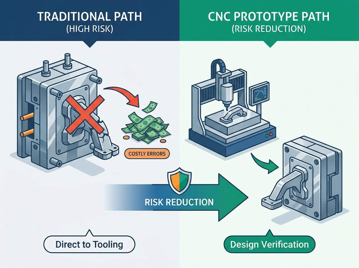
Hardened steel tooling is uncompromising. Once a mold is cut, design changes consume massive amounts of capital and add weeks to the production schedule. Engineering and procurement teams face immense pressure to validate complex part geometries, assembly fit, and functional performance before authorizing capital expenditure for mass production tooling. A single oversight in wall thickness or mating tolerances can render a multi-cavity steel mold useless, requiring extensive welding, electrical discharge machining, or complete tool scrapping.
CNC machining serves as the critical, low-volume validation bridge. By milling prototypes from solid metal billets, engineering teams can physically test their designs before committing to permanent molds. This technical guide details how to use CNC prototypes to identify design flaws, test material equivalents, and secure stakeholder confidence prior to committing to high-volume manufacturing.
CapEx Protection: CNC prototyping acts as an insurance policy against catastrophic tooling errors, allowing for iterative design changes without mold modification costs.
Functional Validation: Machined prototypes enable rigorous physical testing of assembly tolerances, thermal performance, and structural integrity under real-world conditions.
Material Translation: While grain structures differ, selecting the right extruded or billet CNC alloys can closely approximate the mechanical properties of final cast parts.
DFM Alignment: A successful prototype must be designed with final production in mind—ignoring draft angles or uniform wall thickness during the CNC phase creates false confidence.
The Financial Stakes of Die Casting Tooling
Understanding exactly what die casting is establishes the baseline for why tooling requires such high initial investment. In a modern industrial context, it is a high-pressure, high-volume manufacturing process where molten metal is injected under extreme velocity into precision-machined steel molds. These molds are cut from premium H13 tool steel and hardened to withstand severe thermal shock and millions of operational cycles. The sheer physical forces involved dictate that the molds must be incredibly robust. Molten aluminum enters the cavity at pressures exceeding 10,000 PSI. The steel must resist washout, heat checking, and mechanical fatigue.
Premature commitment to tooling carries severe financial and temporal penalties. If a design flaw is discovered after the mold is cut, modifications are rarely simple. Adjusting a tool might require welding new material into the cavity, re-machining, or utilizing sinker EDM to alter slide mechanisms. Welding H13 steel alters its localized hardness, creating weak points susceptible to early failure. In worst-case scenarios, the entire mold must be scrapped. Complex multi-cavity tooling with intricate slide mechanisms represents a massive capital expenditure. Any delay caused by tool rework cascades through the entire product launch schedule, resulting in missed market opportunities and compromised supply chains.
To prevent these errors, engineering teams must satisfy strict success criteria before approving a mold design. Tooling kickoff should only occur when the design demonstrates absolute reliability in the physical world.
Zero interference in the final assembly stack-up.
Thermal dissipation targets physically verified under load.
Weight targets confirmed within acceptable margins.
Structural integrity proven through physical drop and vibration testing.
Sealing surfaces validated for leak-proof operation.
How CNC Machining Validates Die Casting Designs
CNC machining provides the exact physical validation required to confidently approve die casting tooling. By cutting the prototype directly from a solid block of aluminum or zinc alloy, engineers obtain a highly accurate model for rigorous testing. You cannot rely solely on finite element analysis (FEA) or 3D CAD models. Physical parts reveal the hidden realities of manufacturing.
Dimensional accuracy and tolerance testing form the foundation of this validation. CNC machining achieves exceptionally tight tolerances, often up to ±0.005 mm. This precision helps engineers identify the absolute minimum and maximum acceptable dimensions for the final cast part. By testing these extremes, teams can establish realistic tolerance bands for the high-volume production run. If a CNC part machined to the nominal dimension fails to fit the mating component, the cast part will certainly fail. Engineers use these machined prototypes to dial in the exact Geometric Dimensioning and Tolerancing (GD&T) requirements before cutting steel.
Form, fit, and assembly verification require physical integration. A machined prototype allows teams to integrate the component into the broader product assembly. Engineers check for interference issues, verify mating surface flushness, and ensure fastener alignment. Physical assembly often reveals stack-up tolerance issues that 3D CAD models obscure. When you bolt a machined housing to a chassis, you immediately feel if the hole patterns align or if the flanges warp under torque.
Functional, mechanical, and thermal testing push the design to its limits. Machined prototypes endure physical abuse testing. Drop testing, vibration testing, pressure testing, and thermal cycling validate the core geometry. If a thin wall cracks under vibration in the CNC prototype, it will likely fail in the cast version, prompting an immediate design revision. Thermal cameras can monitor a machined aluminum heat sink to verify that the fin geometry dissipates heat as predicted by the software.
Fastener and boss design verification prevents assembly line disasters. Prototypes allow physical testing of self-tapping screws, threaded inserts, and boss wall thicknesses. Driving screws into a machined boss verifies whether the wall thickness is sufficient to prevent stripping or cracking during final assembly. You can measure the exact torque-to-yield point on a machined prototype to set the clutch limits for the assembly line drivers.
Weight reduction and mass properties analysis ensure compliance with strict weight budgets. CNC prototypes verify actual part weight, center of gravity, and mass distribution. This data is critical in automotive or aerospace applications where every gram impacts performance. While the billet material might have a slightly different density than the cast alloy, the physical prototype provides a highly accurate baseline for calculating the final mass.
Material Parity: Evaluating CNC vs. Cast Properties
While CNC prototypes validate geometry, engineers must account for the material differences between a machined billet and a high-pressure cast part. Navigating these alloy equivalents requires a clear understanding of mechanical properties. You cannot assume a 6061-T6 machined part will behave exactly like an A380 cast part.
Property
CNC Billet (Al 6061-T6)
Production Cast (Al A380)
Engineering Implication
Manufacturing Method
Extruded or rolled solid block
High-pressure molten injection
Billet lacks flow marks and knit lines.
Internal Structure
Dense, uniform grain structure
Potential for micro-porosity
Cast parts may leak under high pressure if not impregnated.
Tensile Strength
Higher overall strength (approx 310 MPa)
Slightly lower (approx 324 MPa ultimate, but lower yield)
Adjust safety factors downward for cast parts.
Thermal Conductivity
Excellent (approx 167 W/m-K)
Good (approx 109 W/m-K)
Machined prototypes will run cooler than cast production parts.
Silicon Content
Low (0.4 - 0.8%)
High (7.5 - 9.5%)
Cast parts are harder to anodize cosmetically.
Mechanical property and microstructure variances dictate how prototype data is interpreted. CNC parts machined from billet generally exhibit higher tensile strength. They lack the internal porosity, shrink voids, or cold flows inherent to high-pressure casting. A CNC prototype will inherently be stronger and more structurally sound than the final cast part. The grain structure of a rolled billet is aligned and continuous, whereas a cast part has a more random, rapidly solidified structure.
Engineers must mathematically account for these material differences during prototype testing. If a CNC prototype barely passes a structural load test, the final cast part will likely fail. Safety factors must be adjusted downward when analyzing the strength of the machined prototype to ensure the final cast part is not under-designed. You must apply a derating factor to the physical test results of the CNC part to simulate the weaker cast material.
Surface finish and coating simulation also require careful translation. Post-cast finishes such as anodizing, powder coating, e-coating, or chemical conversion films can be applied to the CNC substrate. This tests cosmetic appearance and environmental resistance. However, you must remember that high-silicon cast alloys like A380 do not anodize as cleanly as 6061 billet. The silicon turns the anodized layer a dark, mottled gray. If your product requires a bright cosmetic anodize, you must test this on actual cast samples later, or switch to a different casting alloy.
Cost-Benefit Analysis: When to Prototype vs. Go Direct to Tooling
Deciding whether to machine prototypes or proceed directly to tooling requires a calculated risk assessment. Volume thresholds and breakeven points provide a framework for this decision. The investment required to machine a batch of 5 to 50 CNC prototypes is easily justified when weighed against the risk profile of a high-volume production run. Spending a small percentage of the tooling budget on CNC prototypes represents a fractional insurance premium against total tool failure.
Lead time trade-offs heavily influence the prototyping strategy. The typical turnaround time for CNC prototypes ranges from 3 to 10 business days. In contrast, tooling fabrication and First Article Inspection (FAI) require 4 to 12 weeks. Discovering a flaw during FAI resets the 12-week clock. Investing a few days upfront for CNC validation protects the broader project timeline from catastrophic delays. You spend a week now to save three months later.
Part complexity directly increases tooling risk. Components featuring undercuts, deep thin walls, complex coring, and multi-part assemblies are notoriously difficult to cast perfectly on the first attempt. The more complex the geometry, the higher the return on investment for a CNC prototyping phase. Simple, flat parts may bypass prototyping, but highly engineered housings demand physical validation. If your part requires multiple side-actions or hydraulic core pulls in the mold, you must prototype it first.
Implementation Risks: The "Un-Castable" Prototype Trap
The most significant risk in this validation process is designing a prototype that is easy to CNC machine but impossible to cast. Machining-only features, such as perfectly sharp internal corners, zero draft angles, and massive variations in wall thickness, create a false sense of security. A prototype that ignores casting constraints is useless for production validation. You will test a part that can never be manufactured at scale.
Integrating Design for Manufacturability (DFM) into the CNC CAD file is mandatory. The prototype must include draft angles, typically ranging from 1° to 3°, appropriate fillets, radii, and uniform wall thicknesses. Even though the CNC mill does not require a draft angle to cut the part, the draft must be machined in to validate the exact geometry and sealing capabilities of the final production unit. If you test an O-ring seal on a perfectly vertical machined wall, it will pass. If the final cast part has a 2° draft on that same wall, the O-ring might fail. You must machine the draft into the prototype.
Simulating tooling mechanics further bridges the gap between prototype and production. The CNC design should incorporate simulated parting lines, gate marks, and ejector pin landing spots. This ensures that cosmetic surfaces and critical sealing areas remain unaffected by the physical marks left by the casting process. Ejector pins leave small indentations. If an ejector pin lands on a critical thermal interface surface, it will ruin the heat transfer. You must map these locations on the CNC prototype to verify they do not interfere with function.
Vendor consolidation offers a strategic advantage in mitigating these risks. Utilizing a single manufacturing partner who handles both the CNC prototyping and the final production tooling ensures seamless knowledge transfer. Shared CAD file history and clear engineering accountability prevent the common scenario where the prototyping shop blames the tooling vendor, and vice versa, for discrepancies. A unified vendor applies the casting DFM rules during the CNC phase, ensuring the prototype accurately reflects the final production intent.
Conclusion
Skipping the prototyping phase to save time usually results in exponential delays and budget overruns during the tooling phase. CNC prototyping remains a mandatory risk-mitigation step for complex parts, ensuring that geometry, assembly fit, and functionality are locked in before steel is cut.
Evaluate manufacturing partners based on their in-house capabilities for both precision machining and high-volume casting.
Demand upfront DFM engineering support to ensure your prototype CAD matches casting realities.
Apply strict casting DFM rules, including draft angles and uniform wall thickness, to your CNC prototype files.
Upload your current CAD files for a dual DFM review to assess both CNC prototype feasibility and long-term tooling viability.
FAQ
Q: What is die casting and why is the tooling so expensive?
A: It is a manufacturing process where molten metal is injected under high pressure into steel molds. The tooling is expensive because it requires premium, hardened H13 tool steels designed to withstand extreme thermal shock and millions of high-pressure injection cycles without degrading.
Q: Can a CNC prototype perfectly match a die cast part?
A: No. While the external geometry and dimensions can be identical, the material grain structure, surface finish, and internal density will differ. CNC parts lack the internal porosity common in cast parts.
Q: Which CNC aluminum alloy is closest to A380 die cast aluminum?
A: Aluminum 6061-T6 is the most common structural stand-in for A380. However, engineers must account for differences; 6061 generally offers higher yield strength and elongation, alongside slightly different thermal conductivity profiles.
Q: Do I need to include draft angles on a CNC prototype?
A: Yes. If the goal is to validate the exact geometry, assembly fit, sealing capabilities, and weight of the final cast part, draft angles must be machined into the prototype to reflect production realities.
Q: How many CNC prototypes should we order before tooling?
A: A realistic range is typically 5 to 50 units. This quantity supports multiple concurrent testing phases, including assembly verification, functional abuse testing, regulatory certification, and beta user testing.
Q: How does prototyping reduce time-to-market if it adds an extra step?
A: It prevents severe tooling rework. Discovering a flaw after a mold is cut can delay a launch by months. The few days spent on CNC prototyping act as a net positive for overall schedule reliability.
With so many years' hard work and development, Ningbo Joyo Metal has built a competitive supply chain in the market to serve the distinguished customers all over the world.
About Us
Your partner for customized metal components/parts manufacturing
 English
 العربية
 Français
 Русский
 Español
 Português
 Deutsch
 italiano
 日本語
日本語 한국어
한국어 Nederlands
 Tiếng Việt
 ไทย
ไทย Polski
 Türkçe
 አማርኛ
አማርኛ ພາສາລາວ
 ភាសាខ្មែរ
 Bahasa Melayu
 ဗမာစာ
ဗမာစာ தமிழ்
தமிழ் Filipino
 Bahasa Indonesia
 magyar
 Română
 Čeština
 Монгол
 қазақ
қазақ Српски
 हिन्दी
 فارسی
فارسی Kiswahili
 Slovenčina
 Slovenščina
 Norsk
Norsk Svenska
 українська
 Ελληνικά
 Suomi
Suomi עברית
עברית Dansk
Dansk Afrikaans
 Gaeilge
 Eesti keel
 latviešu
 Беларуская мова
 Български
 Català
 Lietuvių
 Lëtzebuergesch
 Македонски