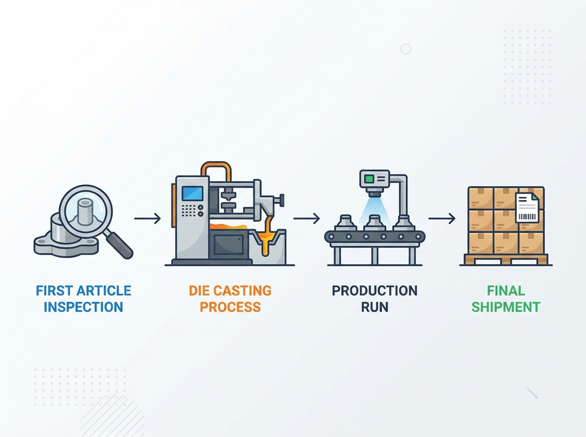
Component failure in high-volume manufacturing carries compounding financial and operational costs. Discovering defects after final assembly is exponentially more expensive than detecting them early during the pressure die casting process. When faulty parts reach the field, the consequences escalate from simple scrap costs to massive product recalls, compromised safety, and severe brand damage. The inherent metallurgical and mechanical variables in metal casting create opportunities for hidden defects. Internal porosity, dimensional drift, and structural weaknesses threaten product integrity and regulatory compliance. These variables require strict control mechanisms to ensure every part meets exact specifications. Without robust oversight, microscopic flaws can propagate into catastrophic failures under operational stress. Implementing a rigorous, multi-stage quality inspection framework is the primary mechanism to de-risk production. This framework transitions the focus from reactive defect sorting to proactive process control. Buyers must carefully evaluate a manufacturer's quality assurance protocols, from initial tooling validation to final batch release.
First Article Inspection (FAI) is the definitive baseline: FAI validates the tooling and process parameters, ensuring the mold is capable of producing parts to exact geometric and metallurgical specifications before mass production begins.
In-process monitoring prevents batch failures: Real-time Statistical Process Control (SPC) during the pressure die casting process identifies parameter deviations (e.g., temperature, injection speed) before they result in physical defects.
Non-Destructive Testing (NDT) is non-negotiable for critical applications: X-ray, CT scanning, and pressure decay testing are required to detect internal porosity and structural voids that surface inspections cannot reveal.
Tooling maintenance directly dictates part quality: Implementing preventative maintenance programs for dies prevents heat checking, washout, and dimensional drift over long production runs.
Vendor evaluation requires auditing their Quality Management System (QMS): A reliable partner must provide transparent traceability, PPAP documentation, and demonstrate strict adherence to ISO and NADCA standards.
The Role of Quality Assurance in the Die Casting Process
Problem Framing (Success Criteria)
A successful production run requires consistent dimensional accuracy, metallurgical integrity, excellent surface finish quality, and zero critical defects across high volumes. Achieving these criteria demands precise control over the entire die casting operation. Manufacturers must establish clear baseline metrics to evaluate output against engineering requirements. Success is measured not just by the first batch, but by the stability of the process over the entire product lifecycle. When setting up a new program, engineers define specific acceptance criteria for every feature on the print. This includes defining maximum allowable porosity sizes in specific zones, surface roughness limits for mating faces, and tight positional tolerances for machined holes. Meeting these criteria consistently across hundreds of thousands of shots separates capable foundries from unreliable suppliers.
Industry Standardization (NADCA Benchmarks)
The North American Die Casting Association (NADCA) standards serve as the industry benchmark for evaluating component quality. These standards define commercial versus precision tolerances, guiding engineers in setting realistic expectations for dimensional accuracy. Adhering to NADCA guidelines ensures that parts meet recognized structural and cosmetic requirements, providing a common language between buyers and manufacturers. For example, NADCA specifies standard linear tolerances based on the alloy used and the dimension's length. Specifying precision tolerances tightens these allowable variations but often requires secondary machining operations or highly specialized tooling adjustments. Understanding these benchmarks prevents over-engineering parts, which drives up manufacturing complexity without adding functional value.
Common Defect Risks
The casting process involves specific physical risks that must be managed. Common defects include gas porosity, shrinkage cavities, cold shuts, misruns, hot tears, and excessive flash. Gas porosity occurs when air is trapped in the molten metal, while shrinkage cavities form during cooling. Cold shuts and misruns result from improper metal flow or temperature control. Identifying and mitigating these risks is central to any quality assurance strategy. Shop floor operators monitor the shot profile to prevent these issues. If the fast shot velocity is too high, turbulence traps air, leading to gas porosity. If the die temperature drops too low, the metal solidifies before filling the cavity, causing a misrun. Each defect points to a specific parameter deviation that must be corrected at the machine control panel.
The Cost of Poor Quality (COPQ)
Inadequate inspection carries a severe business impact. The Cost of Poor Quality (COPQ) encompasses high scrap rates, expensive rework, delayed time-to-market, and premature tool damage. Beyond the factory floor, defective parts can lead to significant liability from field failures. Investing in comprehensive quality control minimizes these financial risks and protects the manufacturer's bottom line. Consider a scenario where an engine cover with internal porosity passes visual inspection but fails during final pressure testing at the assembly plant. The cost of the scrapped casting is minimal compared to the wasted machining time, assembly labor, and the logistical nightmare of sorting suspect inventory across the supply chain.
First Article Inspection (FAI): Validating the Tooling and Baseline
Dimensional Verification via Advanced Metrology
First Article Inspection relies on advanced metrology to verify dimensional accuracy. Coordinate Measuring Machines (CMM) and Structured Blue Light 3D Scanning generate detailed color-map deviations, comparing the first physical parts directly against the original CAD models. This precise measurement identifies any discrepancies in geometry, ensuring the tooling produces parts exactly to specification before mass production begins. A CMM uses a ruby-tipped probe to touch specific points on the casting, verifying hole locations, flatness, and concentricity down to the micron level. Blue light scanning captures millions of data points in seconds, creating a digital twin of the physical part. Overlaying this scan onto the nominal CAD model instantly highlights areas where the tool is cutting heavy or light, allowing toolmakers to make targeted steel adjustments.
Tooling Geometry and Gating System Audit
Validating die design parameters is a critical step in FAI. Engineers audit the gating system, checking gate thickness, runner design, venting paths, and cooling line efficiency. Proper gating ensures optimal metal flow, while effective cooling prevents thermal distortion. This audit confirms that the mold design supports stable, defect-free production. During the initial sampling phase, engineers often perform short-shot testing. By intentionally under-filling the cavity, they can visualize the metal flow front and verify that the gating system fills the part evenly without trapping air. If the flow front is unbalanced, the runner system must be modified before the tool is approved for production.
Material Composition Analysis
Raw material quality dictates final part strength. Optical emission spectrometry (OES) is necessary to verify that the raw alloy chemistry meets exact ASTM or DIN standards before casting begins. Analyzing the material composition ensures the metal possesses the required mechanical properties, preventing structural failures caused by substandard alloys. Foundries take a sample "coin" from the holding furnace and analyze it using the spectrometer. The machine burns the sample with an electrical spark and measures the light spectrum emitted to determine the exact percentages of elements like silicon, copper, magnesium, and iron. If the iron content is too low in an aluminum alloy, the metal will solder to the die steel. If the magnesium content is off, the part may become brittle.
Establishing the Production Baseline
The results of the First Article Inspection dictate final adjustments to the tooling. Once all dimensions and material properties are verified, the parameters for the pressure die casting process are locked in. This established baseline serves as the reference point for all subsequent production runs, ensuring consistency across thousands of cycles. The locked parameters include the slow shot speed, fast shot velocity, intensification pressure, die temperature setpoints, and spray lubrication timing. Any deviation from this approved recipe requires a formal engineering change request. This strict change management prevents operators from making unauthorized adjustments that could compromise part quality.
In-Process Quality Control During the Pressure Die Casting Process
Molten Metal Cleanliness and Melt Control
Pre-injection quality controls are vital for metallurgical integrity. Procedures include rotary degassing validation, density index testing, and spectrographic analysis of the furnace melt. These steps remove impurities and dissolved gases from the molten metal, preventing porosity and ensuring the material is clean before it enters the mold cavity. Rotary degassing involves spinning a graphite rotor in the molten bath while injecting argon or nitrogen gas. The gas bubbles capture dissolved hydrogen and float non-metallic inclusions to the surface, where operators skim them off as dross. A density index test compares the specific gravity of a sample solidified under a vacuum against one solidified at atmospheric pressure, providing a quantifiable measure of the melt's gas content.
Real-Time Parameter Monitoring
Modern casting machines integrate sensors to track critical variables in real-time. Monitored parameters include molten metal temperature, shot sleeve velocity, plunger pressure, intensification pressure, and mold cavity temperatures. Tracking these variables allows operators to maintain optimal conditions and immediately detect deviations that could cause defects. The shot monitoring system generates a curve for every cycle, plotting plunger position against velocity and pressure. Quality engineers set tolerance bands around this ideal curve. If a shot falls outside these limits—perhaps due to a sticking plunger tip or a drop in accumulator pressure—the machine automatically diverts that specific part to a scrap bin, preventing it from mixing with good production.
Statistical Process Control (SPC) Implementation
Manufacturers use Statistical Process Control to monitor process stability. Control charts, such as X-bar and R charts, track variations over time. SPC identifies trends and allows operators to correct tool wear or thermal drift before parts fall out of tolerance. This proactive approach minimizes scrap and ensures consistent quality. Instead of measuring every single part, quality technicians measure a sample of five parts every two hours. They plot the average dimension (X-bar) and the range of variation (R) on the control chart. If the data points start trending toward the upper or lower control limit, the operator knows the process is shifting and can intervene—for example, by adjusting the cooling water flow—before any defective parts are actually produced.
Die Wear and Preventive Maintenance Tracking
Monitoring die wear during production prevents surface finish degradation and dimensional drift. Heat checking, soldering, and washout occur over thousands of cycles. Tracking these wear patterns enables timely preventive maintenance, extending tool life and maintaining part quality throughout long production runs. Heat checking appears as a network of fine cracks on the die surface, caused by the rapid thermal cycling of injecting molten metal and spraying cold lubricant. These cracks transfer onto the casting as raised veins. By tracking the number of shots, toolroom technicians can schedule the die for stress relieving or polishing before the heat checking becomes severe enough to cause part ejection issues or cosmetic rejections.
Automated Optical Inspection (AOI)
Automated Optical Inspection deploys high-resolution cameras and machine vision algorithms on the production line. AOI detects surface anomalies, flash, or ejector pin marks immediately as parts exit the machine. This rapid inspection identifies cosmetic defects early, preventing faulty parts from moving to secondary operations. The vision system compares each part against a master image of a perfect casting. It can detect incomplete fills on thin cooling fins, excessive flash along the parting line, or broken core pins. Implementing AOI reduces reliance on manual visual inspection, which is prone to operator fatigue and subjective judgment.
Non-Destructive Testing (NDT) and Functional Verification for Internal Integrity
X-Ray and CT Scanning for Porosity Detection
Radiographic testing identifies internal gas pockets or shrinkage voids without destroying the component. X-ray and CT scanning map defects against ASTM E505 reference standards, revealing hidden flaws that surface inspections miss. This level of inspection is required for structural parts where internal integrity is paramount. A 2D digital X-ray provides a quick look inside the casting, highlighting voids as dark spots on the image. For complex geometries, a 3D CT scan rotates the part, capturing thousands of X-ray slices to build a complete volumetric model. Engineers use this data to pinpoint the exact location and volume of internal porosity, ensuring it does not fall within critical machined areas or high-stress zones.
Ultrasonic Testing and Dye Penetrant Inspection
Secondary NDT methods detect subsurface cracks and surface-breaking defects. Ultrasonic testing uses high-frequency sound waves to find internal micro-fissures, while dye penetrant inspection highlights surface flaws. These techniques are essential for critical load-bearing parts where even microscopic cracks can lead to failure. In dye penetrant testing, the part is cleaned and coated with a brightly colored or fluorescent liquid dye. The dye seeps into any surface-breaking cracks via capillary action. After wiping away the excess dye, a developer is applied, drawing the trapped dye back to the surface and creating a highly visible indication of the defect.
Leak and Pressure Testing
Functional testing protocols verify components that must hold fluids or gases under pressure. Methods include pressure decay, vacuum testing, and helium mass spectrometry. These tests ensure parts like engine blocks or manifolds maintain hermetic seals, preventing leaks in the final application. In a pressure decay test, the casting is clamped into a custom fixture, sealing all open ports. The internal cavity is pressurized with air, and a highly sensitive transducer monitors the pressure over a set time. If the pressure drops beyond a specified limit, it indicates a leak path through the casting wall, usually caused by interconnected porosity.
Conceptual Trade-offs (Inspection Cost vs. Criticality)
Balancing inspection costs against acceptable risk levels requires a clear decision framework. 100% NDT inspection is expensive but necessary for aerospace components. For consumer electronics, statistical sampling may suffice. The inspection strategy must align with the part's end-use criticality and budget constraints. Implementing automated X-ray inspection on every single part adds significant cycle time and equipment cost. Manufacturers must work with buyers to define the Acceptable Quality Limit (AQL). If a part is a simple bracket, a visual check and a dimensional sample might be enough. If the part is a steering column housing, rigorous NDT is mandatory to prevent catastrophic failure.
NDT Method
Primary Detection Target
Typical Application
X-Ray / CT Scanning
Internal porosity, shrinkage voids
Structural components, safety-critical parts
Ultrasonic Testing
Subsurface cracks, micro-fissures
Load-bearing parts, thick sections
Dye Penetrant
Surface-breaking defects
Machined surfaces, cosmetic parts
Pressure Decay
Leaks, seal integrity
Fluid reservoirs, manifolds, pump housings
Post-Machining, Finishing, and Final Pre-Shipment Verification
Post-Machining Quality Control
After CNC secondary operations, critical mating surfaces, thread dimensions, and tapped holes require rigorous inspection. Technicians use thread go/no-go gauges and precision micrometers to verify tolerances. This step ensures that machined features meet exact specifications for final assembly. Machining removes the dense outer skin of the casting, sometimes exposing subsurface porosity. Inspectors must check machined faces for exposed voids that could compromise gasket sealing. Thread gauges verify that tapped holes have the correct pitch diameter and depth, preventing cross-threading or bolt pull-out during final product assembly.
Surface Finish and Coating Adhesion Testing
Verifying surface roughness and coating durability is essential for finished parts. Protocols include cross-hatch adhesion tests, thickness gauging, and salt spray testing for treatments like powder coating, anodizing, or e-coating. These tests confirm that the finish provides the required corrosion resistance and aesthetic appeal. A cross-hatch test involves cutting a grid pattern through the coating down to the bare metal, applying a specialized tape, and pulling it off rapidly. If the coating flakes off along the cut lines, the adhesion fails, indicating poor surface preparation or improper curing temperatures.
Final Dimensional Audits and Go/No-Go Gauging
Final randomized batch sampling plans, such as ANSI/ASQ Z1.4, ensure overall compliance before packaging. Go/no-go gauging provides a rapid check of critical dimensions. This final audit catches any remaining anomalies, ensuring only parts that meet all specifications leave the facility. Custom inspection fixtures allow operators to drop a part onto locating pins and quickly check multiple features simultaneously using flush-pin gauges or dial indicators. This method is much faster than using a CMM for every part and provides immediate feedback on the shop floor.
Compliance and Certification Documentation
Outbound paperwork provides proof of quality. Required documentation includes Material Test Reports (MTRs), Certificates of Conformance (CoC), and Production Part Approval Process (PPAP) levels 1 through 5. These documents trace the part's history and certify that it meets all engineering and regulatory requirements. A complete PPAP package includes the design records, engineering change documents, dimensional results, material certifications, control plans, and process flow diagrams. This comprehensive documentation proves that the manufacturer has a stable, capable process ready for volume production.
Evaluating a Die Casting Partner’s Quality Management System
Essential Certifications and Traceability Standards
A reliable partner must hold essential QMS certifications, such as ISO 9001, IATF 16949 for automotive, or AS9100 for aerospace. Component-level or lot-level traceability, often achieved through laser-etched barcoding, is non-negotiable. These standards ensure the vendor operates within a structured quality framework. Traceability allows manufacturers to track a specific part back to the exact date, time, machine, and furnace melt it originated from. If a field failure occurs, this data is used to isolate the suspect batch, preventing a massive, untargeted recall.
Preventative Tooling Maintenance Programs
Evaluating a vendor's tool maintenance protocol is critical for long-term quality. Look for shot-limit alerts, regular die stress relieving, and scheduled cleaning intervals. A proactive maintenance program prevents tool degradation, ensuring consistent part dimensions over the life of the project. Ask the vendor how they track tool life. They should have a computerized maintenance management system (CMMS) that automatically flags a die for service after a specific number of shots. This service might include replacing worn core pins, cleaning cooling lines to prevent scale buildup, and re-cutting the gating system if washout has occurred.
Red Flags in Quality Control Proposals
Identify warning signs during vendor selection. Vague inspection frequencies, a lack of in-house NDT capabilities, or a refusal to provide detailed SPC data indicate a weak quality culture. A transparent vendor will openly share their inspection protocols and process control data. If a supplier claims they inspect parts "regularly" without defining the exact sample size and frequency in a formal control plan, walk away. Similarly, if they outsource all their X-ray or CMM work, it creates a feedback loop delay that makes real-time process correction impossible.
Mitigating Supply Chain Risks
Buyers can enforce quality through clear Service Level Agreements (SLAs). Defining Acceptable Quality Limits (AQL) and conducting periodic on-site facility audits hold the vendor accountable. These measures mitigate supply chain risks and maintain high standards throughout the production lifecycle. Schedule an on-site audit and walk the shop floor. Check if the operators are actually filling out the SPC charts at the machines. Look at the scrap bins—are they overflowing, or is the scrap segregated and tracked properly? A clean, organized facility with visible quality metrics is a strong indicator of a capable manufacturing partner.
Conclusion
Reliable die cast part quality cannot be achieved through final inspection alone. It requires a controlled inspection system that begins with First Article Inspection and continues through melt control, real-time process monitoring, tooling maintenance, secondary processing, and final shipment verification.
FAI establishes the approved dimensional, material, and process baseline, while SPC helps detect thermal drift, tool wear, and shot-profile variation before they create large defective batches. X-ray, CT scanning, leak testing, and other NDT methods should be selected according to the part’s structural risk and end-use requirements.
Before shipment, critical dimensions, machined features, coatings, packaging, traceability, and compliance documents must be verified against defined acceptance criteria. The most reliable supplier is one that uses inspection data to maintain process stability—not simply to separate defective parts after production.
FAQ
Q: What is an acceptable porosity level in die casting?
A: Zero porosity is virtually impossible. Acceptable levels are defined by the size, location, and concentration of voids relative to the part's structural requirements, often specified in standards like ASTM E505.
Q: How does the pressure die casting process affect part quality?
A: Injection speed, pressure, and thermal management directly dictate the metallurgical density, surface finish, and dimensional stability of the final part.
Q: What is included in a First Article Inspection (FAI) report?
A: Standard components include material certifications, full dimensional layout against the drawing, functional test results, and process parameter logs.
Q: How do manufacturers test for leaks in die cast components?
A: Manufacturers use pressure decay testing, vacuum testing, and helium leak detection methods for parts requiring hermetic seals, such as pump housings or fluid reservoirs.
Q: What is the difference between destructive and non-destructive testing in casting?
A: NDT methods like X-ray leave the part intact. Destructive methods like tensile testing, sectioning, or impact testing are used to verify mechanical properties on sample batches.
Q: Why is PPAP required for die casting?
A: The Production Part Approval Process provides standardized evidence that the manufacturer deeply understands the design records and that the process can consistently produce parts meeting these requirements.
Q: What are NADCA standards, and why are they important for tolerance control?
A: The North American Die Casting Association standards define standard versus precision dimensional tolerances across common alloys like aluminum, zinc, and magnesium, providing an industry benchmark for quality.
With so many years' hard work and development, Ningbo Joyo Metal has built a competitive supply chain in the market to serve the distinguished customers all over the world.
About Us
Your partner for customized metal components/parts manufacturing

 English
 العربية
 Français
 Русский
 Español
 Português
 Deutsch
 italiano
 日本語
日本語 한국어
한국어 Nederlands
 Tiếng Việt
 ไทย
ไทย Polski
 Türkçe
 አማርኛ
አማርኛ ພາສາລາວ
 ភាសាខ្មែរ
 Bahasa Melayu
 ဗမာစာ
ဗမာစာ தமிழ்
தமிழ் Filipino
 Bahasa Indonesia
 magyar
 Română
 Čeština
 Монгол
 қазақ
қазақ Српски
 हिन्दी
 فارسی
فارسی Kiswahili
 Slovenčina
 Slovenščina
 Norsk
Norsk Svenska
 українська
 Ελληνικά
 Suomi
Suomi עברית
עברית Dansk
Dansk Afrikaans
 Gaeilge
 Eesti keel
 latviešu
 Беларуская мова
 Български
 Català
 Lietuvių
 Lëtzebuergesch
 Македонски