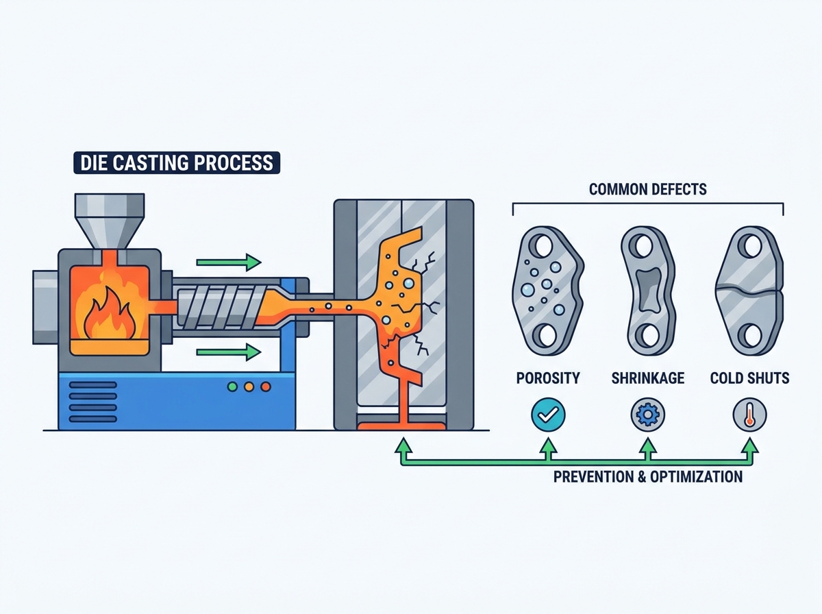
High scrap rates and part failures in high-volume manufacturing carry a compounding financial impact that goes far beyond the initial cost of the rejected component. Unpredictable defect rates compromise structural integrity, delay critical time-to-market schedules, and severely disrupt assembly operations. These issues often stem from misaligned process parameters, inadequate thermal management, or poor tooling design early in the development phase. Shifting the focus from reactive troubleshooting to proactive defect prevention is essential for scaling production reliably. Achieving near-zero defect rates requires rigorous Design for Manufacturability (DFM), advanced process monitoring, and selecting a highly capable manufacturing partner. By understanding the root causes of common casting flaws, engineering teams can implement robust controls that ensure consistent quality and long-term structural performance without relying on endless post-production sorting.
Tooling is the Foundation: Over 70% of structural and cosmetic flaws originate from suboptimal gating, venting, or thermal management in the die design phase.
Process Control Trumps Inspection: Real-time monitoring of injection speed, pressure, and temperature is more cost-effective than relying solely on post-production sorting.
Simulation Mitigates Risk: Utilizing advanced mold flow and thermal simulation software before cutting steel drastically reduces the likelihood of porosity and cold shuts.
Advanced Technologies Exist: Vacuum-assisted die casting and conformal cooling are critical tools for eliminating gas porosity and shrinkage.
Partner Evaluation Requires Technical Scrutiny: Assessing a manufacturer’s internal non-destructive testing (NDT) capabilities and compliance frameworks (e.g., ISO 9001, IATF 16949) is critical for mitigating supply chain risk.
Understanding How the Die Casting Process Works (and Where It Fails)
The Mechanics of High-Pressure Systems
To identify where defects originate, you must understand exactly how the die casting process works on the shop floor. The system relies on injecting molten metal into a precision-machined steel cavity at extremely high speeds and pressures. This rapid injection forces the liquid alloy into complex geometries before it begins to solidify. Establishing this baseline reveals how sensitive the operation is to slight variations in timing, temperature, and kinetic energy. We monitor accumulator pressure drops and plunger velocities in milliseconds because even a minor deviation results in a scrapped part.
Shot Sleeve Dynamics & Air Entrainment
The fill ratio in the shot sleeve during the first phase, known as the slow shot, dictates the initial quality of the metal volume. Low fill ratios leave excessive empty space, trapping air before the fast shot begins. This trapped air is then forced into the mold cavity, introducing built-in gas porosity that compromises the internal structure of the final component. Operators must calculate the exact volume of the biscuit, runner, and cavity to ensure the sleeve is adequately filled before the plunger advances.
Thermal and Kinetic Variables
Achieving complete cavity fill before solidification requires a delicate balance of metal temperature, die temperature, and injection velocity. If the metal cools too quickly upon contacting the die walls, it impedes flow and causes surface defects. Conversely, excessive heat leads to localized shrinkage and tool degradation. Managing these thermal and kinetic variables ensures the metal reaches the furthest extremities of the mold while maintaining structural integrity.
Phase One (Slow Shot): The plunger moves forward slowly to push metal past the pour hole and gather it into a solid mass, minimizing wave formation and air entrapment.
Phase Two (Fast Shot): The accumulator fires, driving the plunger at high velocity to fill the cavity in milliseconds before the metal freezes.
Phase Three (Intensification): Extreme pressure is applied immediately at the end of the stroke to pack out the metal, feeding shrinkage voids as the alloy solidifies.
The PQ⊃2; Equation
The PQ⊃2; diagram serves as the mathematical foundation for matching machine capability to tool gate design. It maps the relationship between pressure (P) and flow rate (Q), allowing engineers to optimize the injection profile. By utilizing the PQ⊃2; equation, manufacturers ensure the machine delivers sufficient power to fill the cavity efficiently without causing excessive turbulence or flashing. You cannot simply put a large tool in a small press and expect good parts; the hydraulics must match the gating thermodynamics.
Critical Failure Points
Defects most commonly occur during specific transitional phases of the injection cycle. The switch from the slow shot to the fast shot must be timed perfectly to prevent air entrapment. Additionally, the application of third-phase intensification pressure is vital. Failure to apply this pressure correctly prevents the metal from packing out the shrinkage as it solidifies, leading to internal voids. If the intensification kicks in even a fraction of a second too late, the gates freeze, and the pressure never reaches the cavity.
Categorizing Common Die Casting Defects
Porosity (Gas and Shrinkage)
Porosity is a primary concern in die casting, generally categorized into gas and shrinkage porosity. Gas porosity results from entrapped air, steam, or vaporized release agents forming spherical voids. Shrinkage porosity occurs when thick sections experience volume reduction during cooling, creating irregular, sponge-like cavities. Both types severely impact part density, pressure tightness, and structural load-bearing capacity. Industry grading standards, such as ASTM E155 reference radiographs, establish acceptable porosity limits for structural components.
Cold Shuts and Flow Marks
Cold shuts occur when two metal fronts meet but fail to fuse completely due to premature cooling or low kinetic energy. This creates a distinct seam or weak point in the casting. Flow marks are similar surface imperfections caused by uneven metal flow. Both defects present significant cosmetic and structural implications, particularly when the part requires secondary surface finishing like plating or powder coating. A cold shut is essentially a pre-existing crack waiting to fail under load.
Blisters and Surface Delamination
Blisters form when trapped gas expands during secondary high-temperature processes, such as T4/T6 heat treatment or powder coat curing, causing the surface to bubble. Surface delamination and cold flakes are often the result of excessive or misapplied die release agents, which prevent the molten metal from bonding properly as it fills the cavity. Over-spraying the die is a common operator error that leads directly to delamination.
Flash and Dimensional Inaccuracies
Flash is the excess metal that seeps between die halves, slides, or ejector pins. It is typically caused by insufficient machine clamping force, excessive injection pressure, or die wear. Flash requires additional secondary machining, increasing production overhead, and interferes with dimensional tolerance compliance, making it difficult to meet strict Geometric Dimensioning and Tolerancing (GD&T) requirements. When flash occurs, it also alters the venting dynamics of the tool, leading to further gas entrapment.
Cracks and Hot Tears
Cracks and hot tears develop from residual tensile stresses generated during uneven cooling and mechanical ejection. Certain geometric features make parts more susceptible to these defects. Sharp internal corners, lack of draft angles, and uneven wall thicknesses concentrate stress as the metal shrinks, leading to structural failure before the part even leaves the mold. Proper radii on all internal corners are non-negotiable for preventing hot tears.
Die Soldering and Drag Marks
Die soldering occurs when the molten alloy chemically bonds with the tool steel, eroding the mold surface over time. This bonding causes drag marks and surface tearing as the part is forcibly ejected. Soldering not only ruins the cosmetic finish of the casting but also causes significant damage to ejector pins and the die cavity, necessitating costly tool maintenance. Maintaining proper die temperatures and ensuring adequate iron content in aluminum alloys prevents soldering.
Common Defect Troubleshooting Matrix
Defect Type
Primary Root Cause
Immediate Corrective Action
Gas Porosity
Trapped air or vaporized lube
Optimize venting, reduce die spray, adjust slow shot speed.
Increase fast shot velocity, raise holding furnace temperature.
Soldering
Overheated die or low iron in melt
Increase die lubrication, verify alloy chemistry, lower metal temp.
Flash
Insufficient clamping force
Verify machine tonnage, check for debris on parting line.
Root Cause Analysis: Why Defects Occur in Production
Tooling and Mold Design Flaws
Inadequate venting, poorly placed chill vents, and improper vacuum-valve locations lead directly to gas entrapment. When air cannot escape the cavity faster than the metal enters, porosity is inevitable. Furthermore, poorly designed gating systems cause turbulent metal flow rather than the ideal laminar or atomized flow, increasing the likelihood of entrapping air and creating surface defects. The gate must direct the metal to wash over the cavity walls, pushing air ahead of it toward the vents.
Suboptimal Process Parameters
Incorrect injection speeds force a trade-off. Speeds that are too fast cause turbulence and gas entrapment, while speeds that are too slow result in premature solidification and cold shuts. Failing to apply sufficient intensification pressure during the third phase prevents the metal from packing out shrinkage voids during solidification. Inconsistent die temperature regulation also disrupts metal solidification rates and accelerates die thermal fatigue, known as heat checking. Operators must rely on thermal imaging and internal thermocouples, not just guesswork, to maintain the die temperature window.
Metallurgical & Melt Quality Failures
Hydrogen gas absorption in the molten bath, particularly in aluminum alloys, causes widespread microscopic gas porosity throughout the casting. The presence of impurities, incorrect iron content levels, and dross inclusions alter the melt's fluidity and mechanical properties. Too little iron causes die attack and soldering, while too much iron makes the final part brittle. Excessive use of recycled scrap metal introduces unpredictable metallurgical variations. Rotary degassing and strict fluxing protocols are required to maintain melt integrity before the metal ever reaches the shot sleeve.
Prevention and Mitigation Strategies for Zero-Defect Manufacturing
Advanced Mold Flow Simulation and Thermal Modeling
Predictive software, such as MAGMASOFT, identifies potential air traps, cold shuts, and thermal hotspots during the DFM phase before any steel is cut. The return on investment for simulation is substantial. It reduces physical tooling iterations, optimizes gate geometry, and accelerates time-to-market by ensuring the mold design is right the first time. We run multiple iterations, adjusting gate thickness and runner angles virtually, to achieve a balanced fill pattern.
Vacuum-Assisted High-Pressure Die Casting (HPDC)
Active vacuum valve systems evacuate air and gases from the mold cavity prior to injection, allowing for virtually gas-free castings. This technology is critical for producing high-integrity structural components. Vacuum casting enables parts to undergo T6 heat treatment and structural welding without the risk of blistering or internal expansion. The vacuum valve must be timed perfectly to close just milliseconds before the molten metal reaches it, preventing metal from entering the vacuum lines.
Thermal Management & Conformal Cooling
Conformal cooling channels, often manufactured using 3D-printed tool steel inserts, allow cooling lines to follow the complex contours of the part. This targets isolated thermal hotspots that traditional straight-line cooling cannot reach. Precise localized cooling eliminates shrinkage porosity in thick sections and maintains a uniform temperature gradient across the die. Managing the delta-T (temperature difference) across the tool surface extends die life and ensures dimensional stability.
Real-Time Process Monitoring and Automation
Implementing sensor-driven shot monitoring systems ensures repeatable pressure, stroke, and velocity profiles for every cycle. Automation plays a critical role in maintaining process stability. Automated ladling, precise die-spray automation, and robotic extraction maintain consistent cycle times, which is essential for preserving the thermal equilibrium of the die. If an operator manually extracts parts, the cycle time varies, the die cools unevenly, and the next shot will likely produce a defective part.
Rigorous Die Maintenance and Lubrication Protocols
Preventative tooling maintenance is necessary to prevent thermal cracking and flash. This includes stress relieving the dies at set cycle intervals to manage fatigue. The application of die lubricants must be highly precise, balancing adequate release properties against the risk of generating gas porosity from vaporized lube trapped in the cavity. Micro-spray systems that apply a highly concentrated, low-volume lubricant are far superior to traditional flood-spray methods.
Evaluating a Die Casting Partner's Quality Control Capabilities
Essential Certifications and Compliance Standards
Verifying a supplier’s Quality Management System (QMS) is the first step in assessing their capability. Focus on ISO 9001 certification as a baseline, and look for automotive or aerospace-specific standards like IATF 16949 or AS9100 for projects requiring stringent process controls and traceability. A certificate on the wall means nothing if the operators on the floor do not follow the control plan.
In-Line and Off-Line Testing Technologies
A capable partner must possess robust testing infrastructure. In-house real-time X-ray and CT scanning are necessary for non-destructive internal porosity inspection. Fluorescent Penetrant Inspection (FPI) detects surface micro-cracks, while metallographic analysis verifies structural integrity. Optical Emission Spectrometry (OES) is used to verify the exact alloy composition of each melt charge. Coordinate Measuring Machines (CMM) and 3D blue-light scanners verify dimensional accuracy against complex GD&T specifications. You need a partner who measures quality with data, not just visual inspections.
Assessing Total Cost of Quality (Scrap Rates vs. Part Price)
Relying solely on piece-part pricing is a flawed procurement strategy. A partner with slightly higher upfront tooling costs—due to investments in vacuum systems, conformal cooling, and flow modeling—consistently yields lower overall production expenses through near-zero scrap rates and reduced secondary machining. Audit a partner's corrective and preventative action (CAPA) processes and review their statistical process control (SPC) charts to ensure they actively manage and improve their quality metrics. If they cannot produce an SPC chart for critical dimensions, they are not controlling their process.
Conclusion
Preventing die casting defects requires controlling the entire production system rather than relying on final inspection alone. Porosity, cold shuts, flash, cracks, and soldering usually result from interacting problems in part design, gating and venting, melt quality, injection parameters, die temperature, and cooling conditions.
Effective prevention begins with a thorough DFM review supported by mold-flow and thermal simulation. During production, stable shot profiles, controlled die lubrication, consistent cycle times, vacuum assistance, and localized cooling help maintain repeatable filling and solidification. Inspection methods such as X-ray, CMM measurement, and statistical process control should then verify that the process remains within defined limits.
When selecting a die casting partner, evaluate its engineering, tooling, monitoring, testing, and corrective-action capabilities—not only its unit price. A controlled process reduces scrap, secondary operations, delivery risk, and total manufacturing cost.
FAQ
Q: What is the most common defect in die casting?
A: Porosity is the most common defect, typically occurring as either gas porosity from entrapped air or shrinkage porosity caused by uneven cooling in thicker sections of the part.
Q: How does vacuum-assisted casting prevent defects?
A: Vacuum systems actively extract air and gases from the mold cavity just before the molten metal is injected, significantly reducing the risk of gas entrapment and resulting porosity.
Q: Why do cold shuts occur?
A: Cold shuts happen when two streams of molten metal meet in the cavity but fail to fuse completely, usually due to low injection speed, low metal temperature, or a cold die.
Q: What causes die soldering?
A: Die soldering occurs when the molten alloy chemically reacts and bonds with the tool steel. It is often caused by inadequate die lubrication, excessive metal temperature, or low iron content in the alloy.
Q: How can mold flow simulation improve part quality?
A: Simulation software predicts how metal will flow and solidify in the mold, allowing engineers to identify and correct potential air traps, cold shuts, and thermal hotspots before manufacturing the physical tool.
Q: What is the purpose of the PQ⊃2; diagram?
A: The PQ⊃2; diagram maps the relationship between machine pressure and metal flow rate, helping engineers match the casting machine's capabilities to the specific gate design of the tool.
Q: Why is consistent cycle time important?
A: Consistent cycle times maintain the thermal equilibrium of the die. Fluctuations in timing alter the die temperature, which can lead to premature solidification, shrinkage defects, or thermal fatigue of the tool steel.
With so many years' hard work and development, Ningbo Joyo Metal has built a competitive supply chain in the market to serve the distinguished customers all over the world.
About Us
Your partner for customized metal components/parts manufacturing

 English
 العربية
 Français
 Русский
 Español
 Português
 Deutsch
 italiano
 日本語
日本語 한국어
한국어 Nederlands
 Tiếng Việt
 ไทย
ไทย Polski
 Türkçe
 አማርኛ
አማርኛ ພາສາລາວ
 ភាសាខ្មែរ
 Bahasa Melayu
 ဗမာစာ
ဗမာစာ தமிழ்
தமிழ் Filipino
 Bahasa Indonesia
 magyar
 Română
 Čeština
 Монгол
 қазақ
қазақ Српски
 हिन्दी
 فارسی
فارسی Kiswahili
 Slovenčina
 Slovenščina
 Norsk
Norsk Svenska
 українська
 Ελληνικά
 Suomi
Suomi עברית
עברית Dansk
Dansk Afrikaans
 Gaeilge
 Eesti keel
 latviešu
 Беларуская мова
 Български
 Català
 Lietuvių
 Lëtzebuergesch
 Македонски